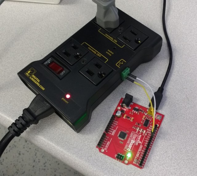
I picked up an ADXL335 accelerometer in a packaging designed to fit onto a solder-less breadboard so that I could interface it to my Arduino. I had a few time-consuming problems interfacing with it because I’m not used to reading chip data sheets.
My assumption was that you’d deliver voltage to it, and it would spit out an analog signal that could be easy translated to acceleration using some constant factor. This isn’t exactly the case. The output resolution, milliVolts per g (1 g = Earth gravity), and voltage bias, is dependent on the voltage delivered to the power pin. I think in hindsight this makes sense, but the data sheet phrases this, and a few other things very peculiarly. I’m fairly inexperienced reading chip data sheets.
The data sheet is here (PDF). On the third page is pretty much everything you need to know to get useful data out of it, and the rest of the doc is stuff most hobbyist level people don’t care about, like how it behaves in different temperatures, and noise expectancy.
The phrase “RATIOMETRIC” shows up a few times. What this means is that a few of the specs are dependent on the power delivered to the chip. The sensitivity (mV/g) is stated to be ratiometric, and the example they give is that when you deliver 3V to the power supply, the sensitivity is 300 mV/g. In a later section called “Use with operating voltages other than 3V” it gives the example of 360 mV/g with a 3.6V power supply, and 195 mV/g with a 2V power supply. You can pretty much gather that the sensitivity in mV/g is the power supply voltage divided by 10. More or less.
Another ratiometric value is the “0g bias”. I don’t do a whole lot of analog electronics stuff, so this took me a bit to figure out. The accelerometer chip can detect negative acceleration, but it doesn’t output a negative voltage signal. What you do is consider the middle point of the power supply voltage range the 0 point. My power supply voltage is 3.3V, so I have to treat 1.6V as the zero point. You’ll add have to subtract that zero point from any voltage reading to get the actual mV/g value.
Here’s some numbers to drive the point home. My power supply is 3.3V, which is 3300 mV. 3300 divided by 10 is 330, so the chip is going to deliver 330 mV per 1g of acceleration. If I have the module on my table with the z-axis point up, it’s going to have 1g of acceleration applied to it, since it’s going to just read the pull of the Earth’s gravity and no other force. The chip’s zero point is the middle of the power supply range, 1.6V (1600 mV), so the actual voltage value it’s going to output for 1g of acceleration is 1930 mV, or 1.93 Volts. Since I know all this, I only need to subtract the zero point voltage to get the true value of 330 mV.
If I turn my accelerometer upside-down, it’s going to feel -1g of force. The voltage it would output would be 1.27V. When you subtract the zero point voltage you get -330 mV, which comes out to -1g.
Anyways, here’s the Arduino code that gets values for the X, Y, and Z axis spit out in units of g.
//Quick accelerometer test
//X is on A0; Y is on A1; Z is on A2

//Analog input pins 0, 1, and 2
//are what I send the x,y, and z
//accelerometer outputs to, respectively
int xAxisPin = A0;
int yAxisPin = A1;
int zAxisPin = A2;

//Variables to hold the returned
//ADC data from the analog input
//pins
int xAxisValADC = 0;
int yAxisValADC = 0;
int zAxisValADC = 0;

//Variables to hold the voltage
//values after converting from ADC
//units to mV
float xAxisValmV = 0;
float yAxisValmV = 0;
float zAxisValmV = 0;

//My Arduino Uno has a 10-bit
//AD converter, with a max value
//of 1023
int ADCMaxVal = 1023;

//The AD converter voltage
//is powered by 5V
float mVMaxVal = 5000;

//I measured the power going to the
//accelerometer as actually being
//3230 mV, so I use this value to
//define the mid-point
float supplyMidPointmV = 3230 / 2;

//Since the supply is actually 3230
//mV, I know the output will be 323mV
//per 1g detected
int mVperg = 323;

//Multiply any acquired ADC value
//by mVPerADC to convert to mV
float mVPerADC = mVMaxVal / ADCMaxVal;

void setup()
{
  Serial.begin(9600);

  //I don't know if setting them to
  //input is necessary, but I do it
  //anyways.
  pinMode(A0, INPUT);
  pinMode(A1, INPUT);
  pinMode(A2, INPUT);

}

void loop()
{
  //Read the x, y, and z values from
  //the analog input pins
  xAxisValADC = analogRead(xAxisPin);
  yAxisValADC = analogRead(yAxisPin);
  zAxisValADC = analogRead(zAxisPin);

  //Convert the ADC values to millivolts
  xAxisValmV = xAxisValADC * mVPerADC;
  yAxisValmV = yAxisValADC * mVPerADC;
  zAxisValmV = zAxisValADC * mVPerADC;

  //This could be prettier. What's happening is the mid-point
  //voltage value is subtracted from the voltage recorded
  //from the analog input, and then that value is divided
  //by how many millivolts per g the accelerometer is
  //ouputing. This results in the value being printed
  //in units of g.
  Serial.print((xAxisValmV - supplyMidPointmV) / mVperg);
  Serial.print("\t");
  Serial.print((yAxisValmV - supplyMidPointmV) / mVperg);
  Serial.print("\t");
  Serial.print((zAxisValmV - supplyMidPointmV) / mVperg);
  Serial.print("\t");

  Serial.println();

  delay(100);
}
It’s a bit verbose, but I wanted to be super clear about what is going on.
I dumped 20 seconds of gathered data into a .txt file and used Excel to make this pretty graph.
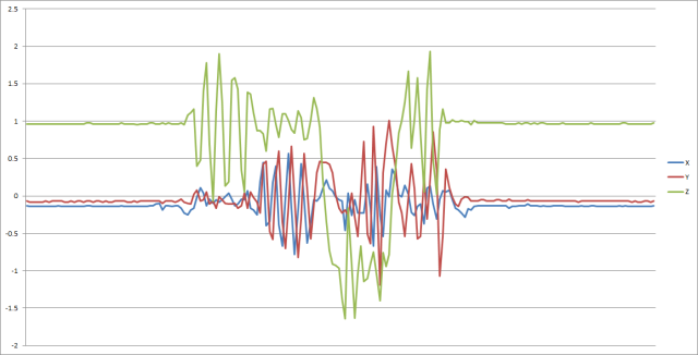
For the first few seconds it’s just sitting on the table, so the z-axis is at 1g, and the x and y-axis are at about 0 (these aren’t calibrated readings, but it’s good enough). You can see when I pick it up and shake it around a bit, then put it back on the table. Neat.
The motivation for writing this post is because it took me about an hour to reconcile the info in the data sheet with the values I was reading on the analog inputs. It was hard to find anything useful online that stated plainly what you need to do on the Arduino end. Hopefully this helps someone out.
Post a comment or message me on Twitter (@cheydrick) if you have any questions.